TTL vs RS232 vs RS485: Choosing the Right Communication Standard for SHM

Infographic comparing TTL, RS232, RS485, and Modbus communication standards, showing distance limits, topologies, and typical applications in electronics and industrial automation.

In the world of electronics, industrial automation, and instrumentation, reliable communication between devices is essential. Several well-established standards define how devices exchange information. Among the most common are TTL, RS232, RS485, and the Modbus protocol. Let’s explore what they are, their limitations, and where they are typically used.


What is TTL?

Transistor-Transistor Logic (TTL) communication is a simple, low-voltage, point-to-point signaling method.

  • Voltage Levels: Logic “0” is typically 0V, and logic “1” is +5V (sometimes +3.3V in modern systems).
  • Use Case: TTL is often found inside microcontrollers, sensors, and development boards such as Arduino or Raspberry Pi.

Limitations of TTL:

  • Not noise-resistant.
  • Short distance only, typically a few centimeters to 1–2 meters.
  • Direct connection between boards; no error checking or addressing.

TTL is best suited for board-level communication where wires are short and interference is minimal.


What is RS232?

RS232 is one of the oldest and most widely used serial communication standards.

  • Voltage Levels: A logic “1” is represented by –3V to –15V, and logic “0” by +3V to +15V.
  • Topology: Point-to-point (one transmitter, one receiver).
  • Common Use: Serial ports on computers, modems, CNC machines, lab instruments.

Limitations of RS232:

  • Maximum cable length is about 15 meters (50 feet) at standard baud rates (up to ~115 kbps).
  • Only supports one-to-one communication.
  • Susceptible to noise and ground potential differences.

Despite its age, RS232 remains popular in legacy equipment and industrial systems.


What is RS485?

RS485 is a differential signaling standard designed for robust and long-distance communication.

  • Voltage Levels: Uses differential pairs (A and B lines) for noise immunity.
  • Topology: Supports multi-drop networks (up to 32 nodes on a single bus).
  • Common Use: Industrial automation, motor controllers, PLCs, and building management systems.

Limitations of RS485:

  • Maximum distance: up to 1200 meters (4000 feet) at 100 kbps.
  • Higher baud rates reduce allowable cable length.
  • Requires proper termination resistors to avoid signal reflections.

RS485 is well-suited for noisy environments and large facilities where multiple devices need to communicate reliably.


Cable Lengths at a Glance

StandardTypical DistanceBaud Rate RangeTopology
TTL< 2 mUp to MbpsPoint-to-point
RS232~15 m (50 ft)Up to ~115 kbpsPoint-to-point
RS485~1200 m (4000 ft)Up to 10 Mbps (shorter distances)Multi-drop bus

What is Modbus?

Modbus is a communication protocol developed in the late 1970s for industrial automation. Unlike TTL, RS232, and RS485 (which are physical layer standards), Modbus defines how data is structured and exchanged.

  • Modbus RTU: Runs over RS485 (most common) or RS232. Data is exchanged in a compact binary format.
  • Modbus TCP: Uses Ethernet for communication.
  • Applications: SCADA systems, PLCs, power meters, sensors, and industrial controllers.

Key Features:

  • Master-slave (RTU) or client-server (TCP) architecture.
  • Widely adopted and supported by thousands of industrial devices.
  • Simple, lightweight, and open protocol.

Final Thoughts

  • TTL is ideal for short, on-board communication.
  • RS232 works well for point-to-point connections over moderate distances.
  • RS485 excels in industrial environments requiring long cable runs and multiple devices.
  • Modbus provides the language on top of RS485 or TCP/IP for structured, reliable data exchange.

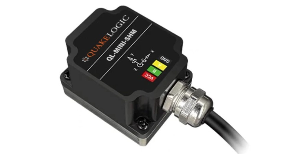
👉 At QuakeLogic, we provide the QL-MINI Series multi-sense sensors, which support TTL, RS232, and RS485 options depending on your intended application. Whether you need short-range board-level integration, reliable point-to-point connectivity, or robust multi-device networking, the QL-MINI line has you covered.
🔗 Explore more here:


AI Robotics Case – Controlling SMD Mobile Robots with Groq

In ACROME Robotics, we are developing easy to understand and easy to replicate content about AI Robotics applications. In our recent articles, we provided an introductory content about using Large Language Model based AI engines in mobile robots. This is a rapid evolving area and we are trying different AI engines and trying to compare their performances. We also published another article, which uses MobileNET SSD’s pre-trained deep-learning models on a small low-cost single-board computer and used these models for visual tracking of objects with a mobile robot built with ACROME’s Smart Motion Devices (SMD) products, which is also a hot area for new updates with new AI tools and algorithms.

What is Groq and why should you consider using Groq for controlling a mobile robot?

Groq is a transformer-based LLM developed by Groq, Inc., a company founded by former Google researchers. Groq is designed to be a highly scalable and efficient LLM, capable of processing large amounts of text data and generating high-quality responses. Groq’s architecture is based on the popular BERT model, but it has several key improvements for performance and flexibility.

Why did we select Groq for this application?

According to Groq, it is more suitable for real-time applications that require fast and accurate text processing, such as chatbots, virtual assistants, and language translation systems. In this application, our goal is to develop a customized “robotics” chatbot indeed. And again, Groq is also well known for applications that require customized solutions, such as fine-tuning for specific tasks and domains.

Using Groq for mobile robot control makes your robot smarter, more flexible, and highly efficient. Compared to traditional programming, an AI-powered system can understand user commands in natural language, thus helping to build more human-centered robotics solutions. With further optimization, the AI can process sensor data, and instantly respond to environmental changes, determine the optimal path, and avoid obstacles while optimizing its movement. Additionally, it can analyze the robot’s sensor data (encoder, current, battery voltage etc.)  to monitor its sub-system performance and predict potential failures before they occur.

With Groq’s high-speed AI models, the decision-making process is accelerated, opening a doorway for seamless remote management and integration with cloud-based control systems. As a result, the robot not only executes predefined tasks but can adapt with latest developments in the AI robotics field and thus can improve its useability and performance.

Controlling Mobile Robots with Groq.AI

The AI-powered autonomous mobile robot combines the simplicity and modularity of ACROME’s SMD platform with the intelligence of Grok AI to deliver smooth motion control and real-time decision-making. The application is developed for educational purposes. However it can be re-used for automation and daily robotics tasks as well.

The robot enables precise motor control, ensuring stability and adaptability in dynamic environments. We have integrated a chatbot connected to Groq AI, allowing real-time communication and intelligent decision-making. The robot can easily be equipped with LiDAR, cameras, and other sensors, enabling obstacle detection and autonomous navigation. Users can interact with the robot via a voice or text-based chatbot, which processes commands and queries Groq AI for real-time data, enhancing the robot’s decision-making capabilities.

Whether used in automated warehouses, smart factories, or customer service environments, this combination provides not only precise movement and scalable electronics, but also interactive engagement, and real-time adaptability. The combination of advanced motor control with ACROME’s Smart Motion Devices products, AI-driven processing, and Groq’s vast knowledge base makes a powerful, intelligent, and efficient robotic system that represents the future of smart automation and AI-integrated robotics.

Code enables remote control of an SMD Red motor through a web-based API, allowing users to manage motor operations with simple commands. It automatically detects the SMD motor via USB connection, establishes communication, and provides functions to start, stop, and adjust motor speed. Users can send commands such as starting the motor at a specific speed, stopping it instantly, or modifying its velocity dynamically. The system integrates Groq AI, which enhances motor performance by predicting movement patterns, optimizing speed adjustments, and ensuring precise control in real time. Additionally, it logs all operations and potential errors in a file for monitoring, troubleshooting, and ensuring smooth execution. By combining SMD motor control with Groq AI-powered optimization, this program provides an efficient, adaptive, and user-friendly solution for automation and robotics applications.

Robot Hardware Details

At the heart of the project lies a mobile robot, built with the modular Smart Motion Devices (SMD) product group. More information is available at the GitBook pages of the SMD products. The SMD products provides an open path for modifications of the robot without barriers.

Here are the major parts of the mobile robot and the details of each item in the project.

• SMD RED Brushed DC Motor Driver from SMD Electronics SetThe robot is equipped with ACROME’s Smart Motion Devices, which provide high torque and precise positioning capabilities. These devices are crucial for the accurate control of the robot’s movements.

• Brushed DC Motors from SMD ElectronicsThe robot uses two DC motors for a differential drive by the SMD RED BDC modules. These motors are responsible for the robot’s mobility, allowing it to perform linear and radial movements as well as rotations. You may check Differential Robot Projects from SMD documentation to learn more about differential mobile robot applications.

• Raspberry Pi: The Raspberry Pi serves as the central control unit, running the Flask API that manages the robot’s commands. It interfaces with the SMD modules through the SMD USB Gateway module and handles the communication with the Client Side PC through a wireless (or sometimes wired for small task) network. SMD products have a native Python API.

• USB Gateway from SMD ElectronicsThe SMD communication network can be connected to the main controller using the USB gateway. This works best with the USB capable host controllers. Alternatively, UART communication (TTL) can be considered with the SMD’s Arduino Gateway Modules.

• Ultrasonic Distance Sensor Module from SMD Electronics: Multiple ultrasound modules (2 or 4) are connected to the robot’s chassis, they are used for preventing collisions. Thanks to the daisy chain connection, the sensors are connected to the SMD RED BDC modules that are close-by. Power and communication is carried with the RJ-45 typed cable, and it reduces the wire clutter and bad connections as well.

• Battery Management System from SMD Electronics: A battery pack powers both the Raspberry Pi and the motors, ensuring consistent operation during the robot’s movement and control processes.

• Mechanical Parts from SMD Building SetThe robot chassis is built with the modular SMD building set parts. Major parts are Plates, Joints and the Wheel set. The mechanical parts have different options and alternative mounting points, which gives users freedom to alter the design with minimal effort.

Software Details

The software enables remote control of the robot through a web-based application, allowing users to manage tasks with simple commands.

Starting with the Wi-Fi connection setup, we establish our communication with the robot using the IP scanner panel.

As the AI part of the robot integrates with the Groq AI, users need to enter their own API key for once, which is used to access users own Groq account.

With the successful connection of the robot and the Groq API, the robot becomes ready for receiving commands from the prompt screen. The system is designed to allow users to control the robot using voice or text-based commands, making it highly interactive. Users can enter their commands either by typing their commands to the “Command” section and click “Send Command” button or by initiating a speech recognition task with the “Start Listening” button.

Currently, the robot executes command in a sequential manner and provides a written feed-back on the application with the result of the command. The application enhances the performance by predicting movement patterns, optimizing speed adjustments, and ensuring precise control in real time. Additionally, it logs all operations and potential errors in a file for monitoring, troubleshooting, and ensuring smooth execution.

This video shows a simple text command entry for controlling the mobile robot built with SMD products and Groq AI:

This video shows a sequence of commands for controlling the same mobile robot:

Tele-operation of the mobile robot with the mobile application (No AI usage in here):

The software is structured to support real-time communication, modular architecture, and extensibility for future updates. The AI part of the application provides functions to start, stop, and adjust motor speed. Users can send commands such as starting the motor at a specific speed, stopping it instantly, or modifying its velocity dynamically.

Client-Side (Android Application)

The mobile application  is built using Flutter  and serves as the primary user interface  for controlling the motion kit. It connects to the Raspberry Pi via Wi-Fi  and provides several key functionalities:

Main Features:

1. Device Discovery & Connection

  – The app scans the local network to find available Raspberry Pi devices running the control software.

  – It filters out non-Linux devices and presents a list for selection.

2. Wi-Fi Configuration & Management

  – Allows users to manually enter network SSID and password.

  – Can switch between predefined network profiles for different locations.

3. AI-Powered Voice & Text Commands

  – Users can enter commands like `”Move forward 50 cm, then turn right”` using speech-to-text conversion.

  – AI processes the command and translates it into precise movement instructions.

4. Manual Control Panel

  – Provides on-screen joystick controls for real-time manual navigation.

  – Displays robot telemetry (battery level, speed, network status).

5. Error Handling & Notifications

  – Detects connection issues and provides user-friendly alerts.

  – If an incorrect command is given, the system suggests alternative phrasing.

Pseudo-Function Design

The pseudo-function design ensures an efficient and structured flow of command execution and feedback. The process is divided into several layers:

Processing Steps:

1. User Input Layer

  – Receives user commands from voice or text input.

2. AI Parsing Layer

  – Converts commands into structured movement instructions.

3. Communication Layer

  – Transmits API requests to Raspberry Pi.

4. Execution Layer

  – Robot processes API commands and executes movement.

5. Feedback Layer

  – Sends motion status and telemetry back to the user interface.

Integration with LLM (Large Language Model)

Integration with LLM (Large Language Model)The project utilizes Groq AI to enable natural language understanding. The AI performs the following tasks:

Key Functionalities:

• Command Breakdown: AI understands and structures complex movement instructions.

• Error Detection: AI identifies ambiguous commands and requests clarification.

• Learning Mechanism: The system adapts to frequently used commands for faster response.

• Multilingual Support: Potentially supports different languages for user interaction.

• LLama-3.3-70B-Versatile Integration: The model enhances processing efficiency, ensuring accurate interpretation and response generation.

Guidance for LLM

To ensure accuracy and robustness, the LLM follows structured guidance principles:

1. Predefined Command Sets

  – The AI recognizes and prioritizes well-defined motion instructions.

2. Context Awareness

  – AI maintains memory of previous commands for sequential movements.

3. Data Logging & Training

  – Command history is stored for continuous improvement of response accuracy.

4. Real-Time Processing

  – AI processes inputs with minimal latency for smooth robot operation.

The User Interface (UI)

The Flutter-based UI is designed to be clean, intuitive, and user-friendly. It consists of:

Main Screens:

1. Home Screen

  – Displays available Raspberry Pi devices for connection.

2. Control Panel

  – Provides joystick-based manual control.

  – Allows AI-based command execution.

3. Settings Screen

  – Wi-Fi configuration options.

  – API key management for AI integration.

4. Telemetry Dashboard

  – Shows real-time sensor data from the robot.

Robot Side of the Software

The robot software runs on Raspberry Pi and serves as the command execution engine.

Core Functions:

– Receives API requests and translates them into movement instructions.

– Controls the motors using the Acrome SMD Python library.

– Manages network configurations for seamless connectivity.

– Executes predefined safety checks to prevent collision.

Flask-Based RESTful API

A Flask-based API  is implemented on Raspberry Pi for handling communication with the client application.

API Functionalities:

– Motion commands (forward, backward, turn left, turn right, stop).

– System diagnostics (Wi-Fi status, battery level, sensor readings).

– Error reporting (command failures, connection issues).

Control Functions Defined in the RESTful API

The API defines various movement control functions that are exposed via HTTP endpoints:

| **Endpoint** | **Functionality** | | `/move_forward?cm=X` | Moves forward by X cm | | `/move_backward?cm=X` | Moves backward by X cm | | `/turn_left?degrees=Y` | Turns left by Y degrees | | `/turn_right?degrees=Y` | Turns right by Y degrees | | `/stop` | Stops all motion |

API Endpoint Structure

Each API endpoint follows a structured format with:

–  Request type: `POST`

–  Parameters: Distance, direction, or angle

– Response: JSON status updates with success/failure messages

Example Request:

“`json { “command”: “move_forward”, “distance”: 50 }

Python Library of the SMD Modules

The Acrome SMD Python library (`acrome-smd`)  is used for precise motor control.

Library Features:

– Low-level motor control

– Velocity and acceleration adjustments

– Custom movement functions

– Error handling and safety limits

Results and Further Reading

Whether you are starting AI robotics tasks, or considering new tools and robotics projects, SMD product family will help you at every level. Feel free to check different level do-it-yourself projects available at SMD Projects documentation page. Contact us for more information or share your own experience.

Admittance Control: Concept, Applications, and Insights

Admittance control is a fundamental control strategy in robotics and mechatronics that governs how a system interacts with its environment. It is designed to make a system respond to external forces by producing a corresponding motion, such as a change in velocity or position, based on a predefined dynamic relationship. This compliance-oriented approach stands in contrast to impedance control, where the system generates a force in response to an imposed motion. Admittance control’s ability to yield to external forces makes it particularly valuable in applications requiring adaptability and safety, such as human-robot collaboration, industrial assembly, and haptic interfaces.

Understanding Admittance Control

At its core, admittance control defines how a system moves in response to an applied force. It is often implemented through a two-loop control structure. The outer loop measures the interaction forces—typically using force or torque sensors—and calculates the desired motion based on a specified admittance model. This model incorporates virtual parameters like mass, damping, and stiffness to shape the system’s dynamic response.

Once the desired motion is determined, the inner loop ensures the system accurately follows the computed trajectory using position or velocity control. This force-to-motion approach is especially suited for robots with precise motion control, allowing them to adjust smoothly to external forces rather than trying to generate counteracting forces directly.

The Admittance control can be split into 3 stages. Outer loop (for measuring the external force/torque), calculation of the admittance model and the inner loop. Let’s dive into each stages hereunder.

1. Force/Torque Measurement (Outer Loop)

For the outer loop there are 2 methods that could be used.

a) Current Estimation:

Current estimation is the process of determining the actual electric current flowing through a system, either by direct measurement or mathematical models. It is commonly used in motor control, battery management, and power electronics to monitor and control current without expensive sensors. By using voltage readings and system models, current can be accurately estimated even without direct measurement.

b) Using a force/torque sensor:

force/torque sensor mounted on the robot’s end-effector or relevant joint continuously measures the forces and torques arising from interaction with the environment. These readings can directly be fed into the outer loop of the control system.

For example, Acrome provides a force/torque sensor option for its Stewart Platform products, as can be seen in the image below. Having a direct sensor measurement simplifies the calculations of the force/torque set points.

Acrome Stewart Platform with a 6D Force-Torque Sensor

2. Calculation of the Admittance Model

The measured force/torque data is input into a predefined admittance model (e.g., Mx¨+Dx˙+Kx=F), where: 

  • M: virtual mass (inertia),
  • D: damping coefficient,
  • K: stiffness coefficient,
  • F: external force,
  • x: position (motion)

The output of this model determines how the system should move, typically in terms of velocity or position.

3. Inner Loop – Motion Execution

In the inner control loop, the robot’s actuators use position or velocity controllers to follow the calculated motion. Instead of counteracting the external force directly, the robot complies with it and adjusts its movement accordingly.

The experimental setup and visual feedback provided to the subjects during the experiments [1]

Applications of Admittance Control

Industrial Robotics

In manufacturing and assembly, robots often need to interact with objects and surfaces in a flexible yet precise manner. Admittance control allows robots to adapt their movement based on physical contact, reducing the risk of jamming or misalignment and improving the efficiency of automated processes.

Human-Robot Interaction in Tesla’s Optimus

In collaborative environments, safety and adaptability are essential. Tesla’s humanoid robot, Optimus, embodies these principles by integrating advanced AI and real-time sensor feedback to interact safely and intuitively with humans. Drawing from Tesla’s Full Self-Driving (FSD) technology, Optimus can perceive its surroundings, predict human motion, and respond accordingly.

One of the key elements in making human-robot interaction seamless is admittance control—a feature Tesla is expected to incorporate into Optimus. This control method allows the robot to sense and react to external forces applied by humans, enabling it to yield or adjust its motion dynamically. For instance, if a human gently pushes Optimus aside while passing through a narrow space, the robot can safely and compliantly give way without resistance or loss of balance.

This kind of responsive behavior is critical in environments where robots and humans share tasks—such as in homes, factories, or healthcare settings. By continuously adjusting its posture and actions based on physical feedback, Optimus minimizes the risk of injury and promotes

trust and collaboration. Tesla’s focus on combining AI perception, motion planning, and human-safe control mechanisms positions Optimus as a powerful example of the future of human-robot collaboration.

Tesla Optimus Robot [2]

Haptic Interfaces

In virtual reality and teleoperation systems, admittance control helps create realistic force feedback. For instance, when using a haptic device, a user might feel the sensation of touching a virtual wall or holding an object. By translating applied forces into controlled movements, admittance control makes digital interactions feel more natural and immersive.

Rehabilitation Robotics

Rehabilitation robots use admittance control to assist patients in physical therapy by adjusting the level of support based on the patient’s movements. This ensures that assistance is provided only when necessary, encouraging active participation and aiding in the recovery process.

Legged Robotics

In legged robots, admittance control helps adjust how the legs respond to different terrains, allowing robots to walk more naturally on uneven surfaces. This improves stability and adaptability in dynamic environments, making it valuable for applications like search-and-rescue or exploration.

Advantages and Challenges

Admittance control offers several benefits, making it a widely used approach. It allows for better interaction with rigid environments, preventing excessive forces that could cause damage [3]. It is also relatively easy to implement on systems with strong motion control capabilities, and the parameters can be adjusted to fine-tune the interaction dynamics.

However, there are also challenges. The approach relies heavily on accurate force sensing, which can be costly and prone to noise, affecting system performance [3]. Stability is another concern—if the system does not respond quickly enough, it can lead to oscillations or instability. To address these limitations, some systems combine admittance control with impedance control, leveraging the strengths of both approaches.

Challenges Due to Orientation-Dependent Force/Torque Sensor Readings in Admittance Control

In admittance control architectures, Force/Torque (F/T) sensors play a crucial role in detecting the external forces applied by the human or the environment. However, these sensors can introduce significant challenges, especially due to their sensitivity to changes in orientation. Since F/T sensors measure forces in their local coordinate frame, any change in the orientation of the robot end-effector may result in a shift of the perceived direction and magnitude of the applied forces. This issue becomes particularly problematic when the center of mass of the attached tool is not aligned with the sensor’s coordinate system, causing gravity-induced forces to project differently depending on the tool’s orientation.

Such effects may lead to misleading force readings, where the sensor interprets gravitational components as user-applied forces. For example, during a drilling task, as the orientation of the robot arm changes, the weight of the drill may create additional force components in unintended axes, potentially degrading the control performance. As highlighted in [4], filtering the raw force measurements and accounting for orientation-dependent effects are essential for stable and transparent human-robot interaction. Proper compensation or transformation of sensor data is therefore necessary to ensure that the control system accurately interprets external inputs and maintains safe and intuitive behavior​. 

Conclusion

Admittance control is a powerful and flexible method that enhances how robots interact with their environment. Whether in manufacturing, healthcare, or human-robot collaboration, its ability to adapt to external forces makes it a critical tool in modern robotics. While challenges like force sensing and stability remain, continuous advancements are refining its implementation, ensuring its continued relevance in future robotic applications. By blending precision with adaptability, admittance control plays a key role in shaping the next generation of interactive robotic systems.

Resources:

[1] Y. Aydin, O. Tokatli, V. Patoglu, and C. Basdogan, “Stable Physical Human-Robot Interaction Using Fractional Order Admittance Control,” in IEEE Transactions on Haptics, vol. 11, no. 3, pp. 464-475, 1 July-Sept. 2018, doi: 10.1109/TOH.2018.2810871.

[2] “Optimus (robot),” Wikipedia: The Free Encyclopedia, https://en.wikipedia.org/wiki/Optimus_(robot) (accessed Apr. 20, 2025).

[3] A. Q. Keemink, H. van der Kooij, and A. H. Stienen, “Admittance control for physical human–robot interaction,” The International Journal of Robotics Research, vol. 37, no. 11, pp. 1421–1444, Sep. 2018, doi: 10.1177/0278364918768950.

[4] A. Madani, P. P. Niaz, B. Guler, Y. Aydin and C. Basdogan, “Robot-Assisted Drilling on Curved Surfaces with Haptic Guidance under Adaptive Admittance Control,” IEEE/RSJ International Conference on Intelligent Robots and Systems (IROS), Kyoto, Japan, 2022, pp. 3723-3730, doi: 10.1109/IROS47612.2022.9982000. 

[5] D. Sirintuna, Y. Aydin, O. Caldiran, O. Tokatli, V. Patoglu, and C. Basdogan, “A Variable-Fractional Order Admittance Controller for pHRI,” IEEE International Conference on Robotics and Automation (ICRA), Paris, France, 2020, pp. 10162-10168, doi: 10.1109/ICRA40945.2020.9197288.

[6] Y. Sun, M. Van, S. McIlvanna, N. N. Minh, S. McLoone, and D. Ceglarek, “Adaptive admittance control for safety-critical physical human-robot collaboration,” *IFAC-PapersOnLine*, vol. 56, no. 2, pp. 1313-1318, 2023, doi: https://doi.org/10.1016/j.ifacol.2023.10.1772. 

[7] C. T. Landi, F. Ferraguti, L. Sabattini, C. Secchi, and C. Fantuzzi, “Admittance control parameter adaptation for physical human-robot interaction,”IEEE International Conference on Robotics and Automation (ICRA), Singapore, 2017, pp. 2911-2916, doi: 10.1109/ICRA.2017.7989338. 

[8] H. Zhan,  D. Ye, C. Zeng, and C. Yang, “Hybrid variable admittance force tracking and fixed-time position control for robot–environment interaction,” Robotic Intelligence and Automation, vol. 45, no. 1, pp. 1-12, 2025. doi: 

[9] ARISE Project, “Advanced AI and robotics for autonomous task performance,” Horizon Europe Project 101135959, [Online]. Available: https://cordis.europa.eu/project/id/101135959

[10] Y. Aydin, O. Tokatli, V. Patoglu and C. Basdogan, “A Computational Multicriteria Optimization Approach to Controller Design for Physical Human-Robot Interaction,” in IEEE Transactions on Robotics, vol. 36, no. 6, pp. 1791-1804, Dec. 2020, doi: 10.1109/TRO.2020.2998606.

[11] A. Madani, P. P. Niaz, B. Guler, Y. Aydin and C. Basdogan, “Robot-Assisted Drilling on Curved Surfaces with Haptic Guidance under Adaptive Admittance Control,” IEEE/RSJ International Conference on Intelligent Robots and Systems (IROS), Kyoto, Japan, 2022, pp. 3723-3730, doi: 10.1109/IROS47612.2022.9982000. 

[12] Y. M. Hamad, Y. Aydin and C. Basdogan, “Adaptive Human Force Scaling via Admittance Control for Physical Human-Robot Interaction,” in IEEE Transactions on Haptics, vol. 14, no. 4, pp. 750-761, 1 Oct.-Dec. 2021, doi: 10.1109/TOH.2021.3071626.

[13] B. Guler, P. P. Niaz, A. Madani, Y. Aydin, C. Basdogan,

“An adaptive admittance controller for collaborative drilling with a robot based on subtask classification via deep learning,” in Mechatronics, vol. 86, 102851, 2022, doi: https://doi.org/10.1016/j.mechatronics.2022.102851.

[14] F. Dimeas and N. Aspragathos, “Online stability in human-robot cooperation with admittance control,” IEEE Transactions on Haptics, vol. 9, no. 2, pp. 267–278, Apr./Jun. 2016.

[15] J. E. Colgate and N. Hogan, “Robust control of dynamically interacting systems,” International Journal of Control, vol. 48, no. 1, pp.  65–88, 1988.

[16] S. P. Buerger and N. Hogan, “Complementary stability and loop shaping for improved human–robot interaction,” IEEE Transactions on Robotics, vol. 23, no. 2, pp. 232–244, Apr. 2007.